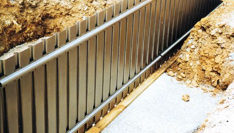
Fundamentseitenschalungssysteme
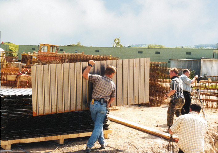
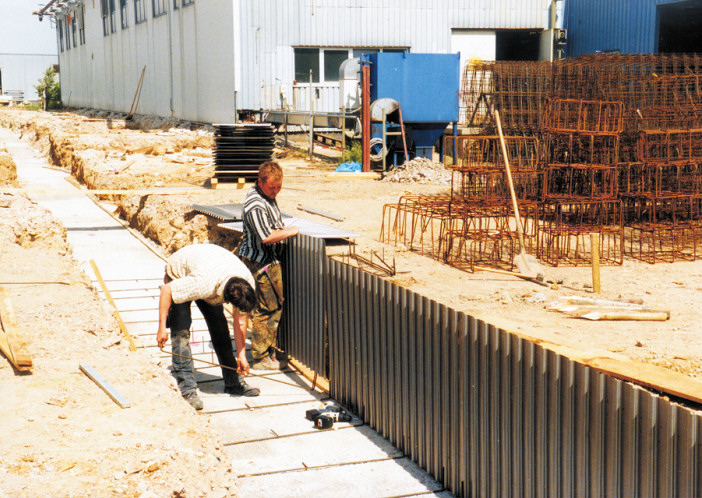
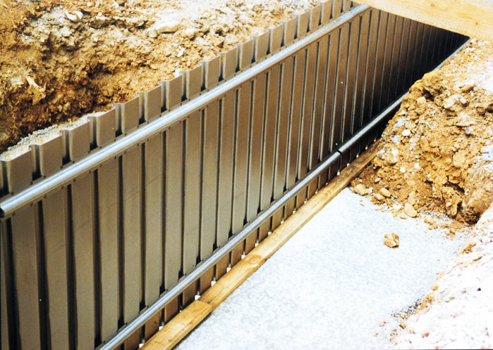
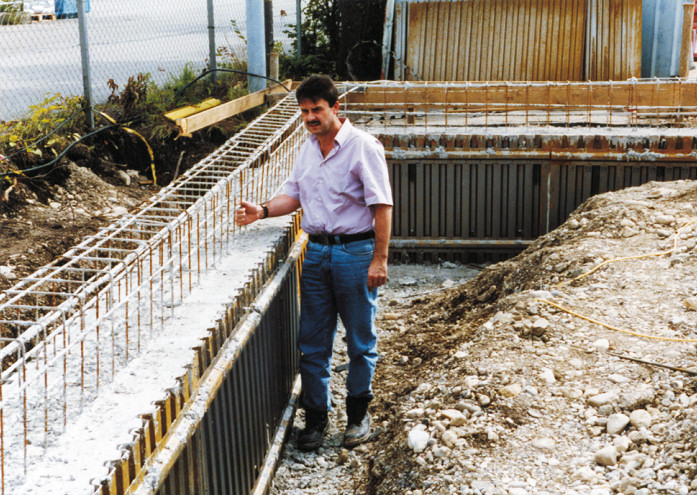
Technical specifications type FS 2001:
| Element length with overlapping: | 3.1 m |
| Element length actual: | 3.05 m |
| Element height: | according to specifications |
| Profiling of lateral wall: | 35-58/26 mm |
| Push-in brackets: | ø 10 mm |
| Recommendation for bracket distance: | approx. 50 cm |
| System components: | 2 (Casing + bracket) |
| Weight per sqm: | approx. 8 kg |
| Free-standing cement height: | to 1 m |
| Available in radius: | yes |
| Available with base plate laying: | yes |
| Delivery time per casing: | approx. 5 wor days (by arrangement) |
| Assembly times: | approx. 0.1 h/qm |
Trapezoidally profiled foundation shuttering type FS 2001
Advantages type FS 2001:
- saves a lot of time
- allows reinforcement installation without hindrance
- elements are long but light
- makes cranes unnecessary
- makes sorting shuttering accessories unnecessary
- shuttering elements can be used for interior and
- exterior foundations
- system consists solely of walls and the upper and
- lower insertible connectors
- parts can easily be shaped on site
- no need to strip the framework after use
- no need to move shuttering
- is very quickly supplied
System specifications type FS 2001
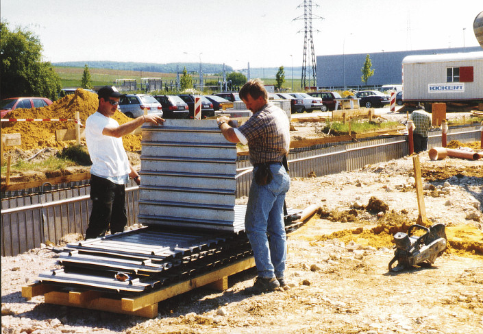
MSL FS 2001 foundation shuttering consists of only two components:
- Foundation wall shuttering element
- Insertible connector
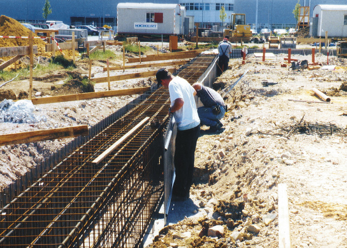
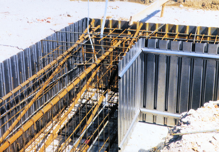
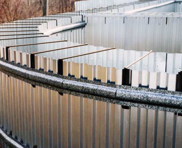
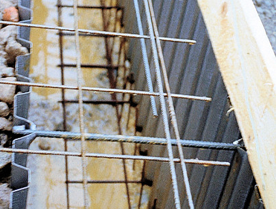
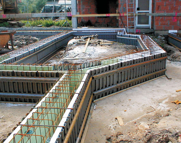
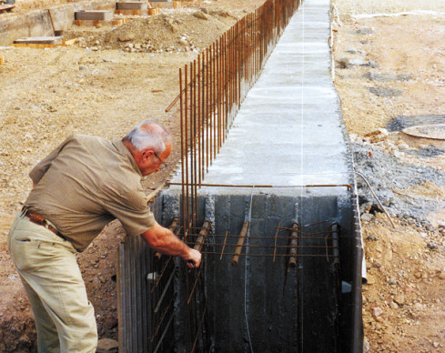
The 3.1 meter lightweight foundation wall shuttering element adheres to its shape thanks to 27 vertical trapezoidal profiles. A trapezoidal cross profile is permanently welded to the upper and lower parts of the shuttering exterior. Inserting the connectors in the trapezoidal profiling at top and bottom fixes the foundation wall shuttering elements in their predetermined spacing. A major advantage of this shuttering is that the reinforcement can be installed on the foundation course without hindrance in advance once the lower connector has been inserted. Reinforcement can also be installed after the first wall has been put up (see illustration 4).
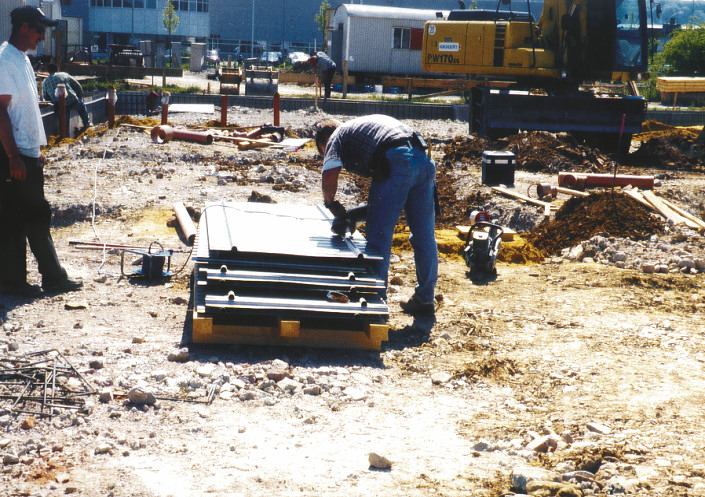
Shaped parts such as e.g. corner elements can be easily and quickly made by the client making cuts in the two permanently welded cross profiles. Radial design is feasible by making cuts in the cross profiles (see illustration 8). After cutting the cross profiles the elements are simply bent into the shape desired (see illustrations 5 to 7).
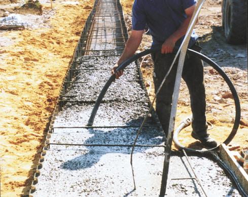
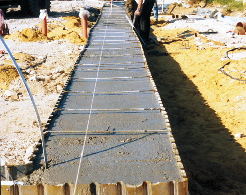
The freestanding shuttering can be filled with concrete all round in two to three steps up to an element height of one meter.
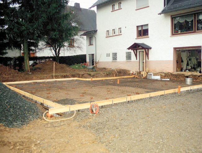
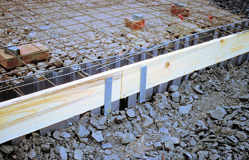
We recommend the client connect the shuttering overlaps with three or four self-tapping screws in each case. Since the shuttering is temporary we recommend supporting it externally using normal earth fill. The base plate and the foundations can be shuttered simultaneously (please refer to the FS 2001 light specifications on this). Another client variation for base plates is shown in photos 9 to 11.
Client affixing in place of shuttering is by a connecting bracket developed by MSL that is inserted in the upper trapezoidal profiling. Photo 12 shows foundation insulation installed by a client.
The freestanding shuttering can be filled with concrete all round in two to three steps up to an element height of one meter (see photos 13 to 16).


